odop
Open Design Optimization Platform (ODOP) - Coil spring design app; mechanical springs; compression spring, extension spring, torsion spring
Compression Spring Design Type

The Compression Spring design type is a full-featured mathematical model enabling the engineering design of round wire helical coil compression springs.
This section presents material unique to the Compression Spring design type. The more general material available at Spring Design Topics provides important supplemental information.
On this page:
- Compression spring variable names on Force-Deflection diagram
- Compression Spring Variable Names on image of physical spring
- Compression spring Force-Deflection point names
- Independent Variable names
- Dependent Variable names
- Calculation Input names
- Values in reports
- Constraints unique to compression springs
- Compression spring end types
- Dead Coils
- User specified end type examples
- Buckling
- Shot Peen
- Related topics
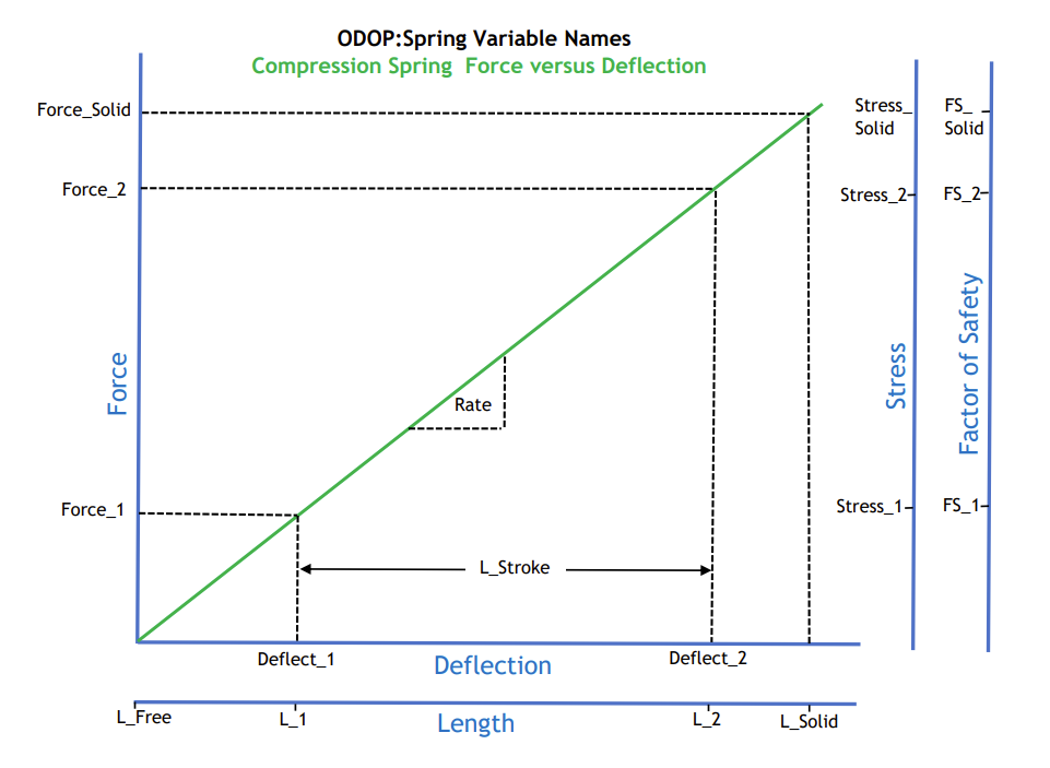
Compression spring variable names on Force-Deflection diagram

Full size image: Compression Spring Variable Names on Force - Deflection Diagram
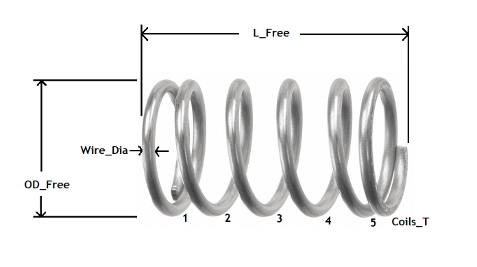
Compression Spring Variable Names on image of physical spring

Compression spring Force-Deflection point names
The compression spring Force-Deflection points and associated names are:
| length | force | outside diameter | inside diameter | stress | factor of safety | |
|---|---|---|---|---|---|---|
| free: | L_Free | OD_Free | ID_Free | |||
| point 1: | L_1 | Force_1 | Stress_1 | |||
| point 2: | L_2 | Force_2 | Stress_2 | FS_2 | ||
| solid: | L_Solid | Force_Solid | Stress_Solid | FS_Solid |
point 1 = minimum operating load point 2 = maximum operating load
Independent Variable names:
| Name | Description | |
|---|---|---|
| Wire_Dia | wire diameter | |
| OD_Free | outside diameter in the free condition | |
| Coils_T | total number of coils, including inactive coils | |
| L_Free | free length | |
| Force_1 | load at point 1 (minimum operating load) | |
| Force_2 | load at point 2 (maximum operating load) |
Dependent Variable names:
| Name | Description | |
|---|---|---|
| Mean_Dia | mean diameter of spring coil in free condition (OD_Free + ID_Free)/2 | |
| Coils_A | number of active coils (turns) | |
| Rate | spring constant - force per unit deflection | |
| Deflect_1 | deflection at Force_1 | |
| Deflect_2 | deflection at Force_2 | |
| L_1 | spring length at minimum operating load (Force_1) | |
| L_2 | spring length at maximum operating load (Force_2) | |
| L_Stroke | net deflection between point 1 and point 2 | |
| L_Solid | solid height | |
| Slenderness | ratio of L_Free to Mean_Dia. The "form factor" that governs a spring's tendency to buckle | |
| ID_Free | inside diameter in free condition | |
| Weight | weight of spring; wire density * wire volume | |
| Spring_Index | spring index; the ratio Mean_Dia/Wire_Dia | |
| Force_Solid | force produced in solid condition | |
| Stress_1 | torsional stress at point 1 | |
| Stress_2 | torsional stress at point 2 | |
| Stress_Solid | torsional stress in the solid condition | |
| FS_2 | static factor of safety at point 2. This is the ratio of allowable stress to the calculated stress induced by the load at point 2 (Stress_Lim_Stat/Stress_2). | |
| FS_Solid | static factor of safety at solid condition (Stress_Lim_Stat/Stress_Solid) | |
| FS_CycleLife | factor of safety based on the Soderberg endurance limit calculation. This figure uses the allowable endurance stress (Stress_Lim_Endur) to include fatigue considerations. Refer to additional discussion in the Cycle_Life topic. | |
| Cycle_Life | expected cycle life based on a calculation using the "modified Goodman method". This value is approximate. Refer to additional discussion in the Cycle_Life topic. | |
| %_Avail_Deflect | the percentage of available deflection consumed at load point 2. | |
| Energy | change in elastic potential energy between point 1 and point 2. |
Calculation Input names
| Name | Description | |
|---|---|---|
| Spring_Type | character string used only as a label | |
| Prop_Calc_Method | Property Calculation Method controls how material properties and allowable stresses are determined. See also: Materials. | |
| 1 - indicates values come from materials table; allowable stresses will be calculated as a function of Wire_Dia. | ||
| 2 - indicates tensile and allowable % are supplied by the user; allowable stresses are calculated. | ||
| 3 - indicates allowable stresses are supplied directly by the user. | ||
| Material_Type | selects an entry in the material table. Is used to determine allowable stresses when Prop_Calc_Method is 1. Otherwise is ignored. | |
| ASTM/Fed-Spec | character string used only as a label to further identify the origin of material property data | |
| Process | character string used to identify the manufacturing process. It is normally controlled by the material selected from the material table. Values are usually Cold_Coiled or Hot_Wound. See also: Hot_Factor_Kh (below). | |
| Life_Category | This value reflects the user's input about shot peening and required cycle life. It is input to the calculation of FS_CycleLife. See also: Cycle_Life | |
| Density | wire density; weight per unit volume | |
| Torsion_Modulus | torsional modulus (G); a.k.a. shear modulus or modulus of rigidity | |
| Hot_Factor_Kh | empirical correction factor applied to hot wound modulus | |
| Tensile | tensile strength | |
| %_Tensile_Endur | allowable fraction of tensile strength for torsion endurance (cyclic load) See also: Cycle_Life | |
| %_Tensile_Stat | allowable fraction of tensile strength for torsion static load | |
| Stress_Lim_Endur | allowable stress limit; cyclic application (torsion) | |
| Stress_Lim_Stat | allowable stress limit; static application (torsion) | |
| End_Type | character string that is used to determine calculations for Inactive_Coils, L_Solid and Pitch; See also: Compression spring end types | |
| Inactive_Coils | number of inactive coils (depends on End_Type) | |
| Add_Coils@Solid | extra coils included in solid height calculation; See also: Compression spring end types | |
| Catalog_Name | name of the catalog containing the most recently selected catalog entry | |
| Catalog_Number | catalog number of the most recent catalog entry |
Values in reports
Other values calculated and displayed in the Reports include:
| Name | Description | |
|---|---|---|
| Wire Length | total length of wire required to manufacture the spring, not including any waste | |
| Safe Load | The load supported by the spring in the solid condition or at a stress equal to the Stress_Lim_Stat value, whichever is lower. | |
| Pitch | distance between the wire centers of adjacent coils, measured in the free state | |
| Weight | weight of 1,000 springs | |
| Buckling | indication of tendency to buckle given the current design and loading conditions | |
| Stress Ratio | ratio of minimum stress to maximum stress (Stress_1/Stress_2) | |
| Kw1, Kw2 | stress correction factors due to curvature | |
| Helix Angle | angle, in degrees, of the spring helix relative to a perpendicular to the spring axis |
Constraints unique to compression springs:
Slenderness
Slenderness is a compression spring's ratio of free length (L_Free) to mean coil diameter (Mean_Dia). If this ratio exceeds 4 for a compression spring, that spring will have a tendency to buckle under load. In that case, the spring will usually need support in the form of a sleeve or post. In order to restrain the search to select designs that do not have a tendency to buckle, set the value of Slenderness MAX to a value of 4.0 or less.
For additional information, see: Buckling
%_Avail_Deflect
%_Avail_Deflect is the percentage of available deflection consumed at load point 2. %_Avail_Deflect is usually constrained to be less than 85 to 98 percent. Thus, it requires the search to select designs that provide a small margin between load point 2 and the solid condition.
End Types
ODOP:Spring currently implements six spring end types for compression springs. In addition, the user can define specialized end conditions. For compression springs, the Calculation Input End_Type has the following possible values:
| Compression spring end types | |
|---|---|
| 1 | Open |
| 2 | Open&Ground |
| 3 | Closed |
| 4 | Closed&Ground |
| 5 | Tapered_C&G |
| 6 | Pig-Tail |
| 7 | User_Specified |
For a compression spring, the end type selection directly impacts the value of Inactive_Coils and Add_Coils@Solid. L_Solid, Pitch and other variables are impacted indirectly.
When End_Type is set to one of the standard (non User_Specified) selections, Inactive_Coils and Add_Coils@Solid will be set by the program from values contained in internal tables. When the value of End_Type is User_Specified, the user may set these values by making an entry in the corresponding numeric entry field.
Add_Coils@Solid
In order to facilitate the treatment of less common compression spring end types such as the "Tapered, Closed and Ground" configuration associated with hot wound springs, ODOP:Spring has added an extra term into the solid height calculation. Add_Coils@Solid is a constant that is normally determined by the value of End_Type. It is used to separate the solid height calculation from the rate equation which is dependent on the value of Inactive_Coils. Add_Coils@Solid represents the number of wire diameters added into the solid height beyond Coils_T. For Open and Closed end types, it has a value of +1.0. For Open&Ground and Closed&Ground end types, it has a value of 0.0. For the Tapered_C&G end type, Add_Coils@Solid has a value of -0.5.
Note that the Add_Coils@Solid term is not included in Coils_T or the wire length and weight calculations. It is only an adjustment for the solid height calculation and is not the correct way to represent Dead Coils.
The Add_Coils@Solid term may be used to represent unusual end configurations. For example, springs that have a different end type at each end. To establish the value of Inactive_Coils and/or Add_Coils@Solid directly, first select a value of End_Type of User_Specified.
Dead coils
In a compression spring, "dead coils" are additional close wound coils, typically placed at each end. Dead coils can be effective in preventing tangling.
The appropriate way to handle dead coils is to select the "User_Specified" end type and increase the value of Inactive_Coils by the desired number of dead coils.
User specified end type examples
To represent a spring with one end Closed and with the other end Closed&Ground:
CHANGE  End_Type  User_Specified
CHANGE  Inactive_Coils   2.0
CHANGE  Add_Coils@Solid  0.5
To represent a spring with ten active coils, two dead coils and closed ends:
CHANGE  End_Type  User_Specified
FIX Coils_T     14.0
CHANGE  Inactive_Coils   4.0
CHANGE  Add_Coils@Solid  1.0
Buckling
A compression spring intended for operation without lateral support should have a ratio of free length to coil diameter (Slenderness) less than approximately 4 to avoid buckling. For designs with a greater Slenderness ratio, lateral support is usually provided by operation in a sleeve or over a post.
                 free length          L_Free
Slenderness = ----------------  =  -------------
                coil diameter        Mean_Dia
The constraint Slenderness MAX can be used to restrict the search to designs that will not tend to buckle. Note that Slenderness is not constrained in the default startup design. Thus, unless this constraint is established, a search may produce designs that are subject to buckling.
The Report tabs will provide an indication as to the possibility of bucking for each specific design and loading condition. Both the fixed-free and fixed-fixed end conditions are covered.
More precise treatments of this subject are available in the resources listed in the Spring Design References section of the documentation.
Shot Peen
Coil springs may be shot peened in order to introduce favorable (compressive) stress at the surface. This improves cycle life at the cost of a secondary operation during manufacturing.
The Calculation Input Life_Category allows the user to specify that the spring will be shot peened.
Selecting a non-default Life_Category that describes a shot peened spring in a cyclic application works with the built-in materials table to select a value for Stress_Lim_Endur. As described in Cycle Life, to get the desired impact on the final spring design, it is important to also enable the constraint on FS_CycleLife.
See also:
Related topics