odop
Open Design Optimization Platform (ODOP) - Coil spring design app; mechanical springs; compression spring, extension spring, torsion spring
Procedure to create tooltip images
This entry provides a summary of procedures used to create the ODOP tooltip images.
Additional documentation of tooltip image work can be found in GitHub issues / branches 897:
Add images to variable name tooltips #897
and 925:
Add more images to variable name tooltips #925
From issue 897:
Design guidelines for tooltip images
- images to be 160 pixels wide by minimum height necessary to get the job done
- spring images to correspond with design type (compression, extension, torsion)
- use the initialState spring dimensions (proportions) with reduced coil count as basis for rendered images
- coil count should be an integer (not fractional); perhaps 3 or 4
- to the extent possible, keep spring dimensions, orientation, coil count, etc. consistent between tooltip images
- to the extent practical, avoid or reduce text in the image
- use rendered spring images (FreeCAD rendering of imported IGES files?)
- green witness lines; turquoise dimension lines
- rendered spring images to be gray
- if multiple springs in one image, use light gray to distinguish the "for reference" instances
- Use open arrows to illustrate forces, curved open arrows for moments; size of arrows to reflect relative size of force
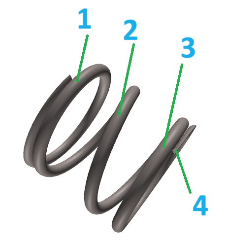
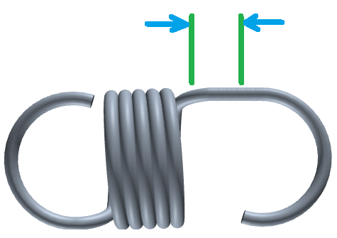
Example images


Procedure
- Use an image editor. Most of the first generation images were manipulated with Windows 11 Paint.
- As appropriate, capture a base image of a helix. Convert to gray if necessary. Scale to roughly 500-600 pixels wide. Arbitrary height.
- Make desired annotations
- Save as large (_lg suffix) version
- Scale to 160 pixels wide, corresponding height
- Save as regular tooltip size (no suffix)
Place the images in (for example): /public/designtypes/Spring/<type>/tooltips/